


Stray voltage, or “leakage current” as we prefer to call it, is an issue becoming more prevalent in the dairy industry. As our industry utilizes more electronic equipment that increases the efficiency of our operations and reduces operating costs, such as variable speed drives (VSDs), electronic ballast lighting, variable speed fans and ventilation, we are actually increasing the sources of possible stray voltage. Faulty wiring, defective equipment, bad connections and electrical arcs are also sources that may cause stray voltage on a facility at any time.
The above are examples of on-farm sources, but we must also be concerned about off-farm sources. They are also becoming more prevalent as electrical usage increases throughout the electrical network.
Stray voltage is simply unwanted current flowing on the grounding network of a facility. This phenomenon exists everywhere in North America; however, it is found in different quantities and can originate from various sources.
In a factory or any industrial facility, unwanted current is, in some cases, purposely redirected to the grounding network and this causes no major problems.
When animals are present (like on a dairy facility), since the animals are in contact with the grounding network, current flowing on the grounding system is just not acceptable.
Studies have confirmed that if a voltage potential is high enough to allow +3mA at 60Hz to flow in the body of a cow, the animals can be uncomfortable and stressed. In a dairy animal, stress can lead to many behavioral and health issues.
We consider that no matter the source, be it external (off-farm) or internal (on-farm), or no matter its frequency range, the impact on the animal would be the same.
The variety of electrical networks on livestock farms in North America has led us to establish a measurement protocol well-suited to fit any configuration of electrical networks.
The main goal is not only to identify the presence of a problem but to clearly identify the source of the problem as well. To accomplish this, a full electrical analysis of the facility must be performed. On-farm and off-farm sources must be identified.
The importance of correcting both off-farm and on-farm sources cannot be overstated. The impact on the animal from either source will be the same.
The process of measuring the electrical network and analyzing the data must be done before issues can be resolved. Using proper tools to accomplish the analysis that supply needed data is most important. Here’s an introduction to some of the equipment that can be used for such an analysis.
Ground resistance measurements of the facility
We developed an evaluation method of the ground resistance of a livestock building, from a validated algorithm.
By integrating the resistance of the main neutral conductor, covered distance and outside temperature, and taking into account the impact of motor start-ups on the electrical network, the computerized measurement protocol determines with a high degree of accuracy the equivalent grounding resistance of a livestock building and, if necessary, the resistance of the distribution network of the electric utility.
The results from this testing enables us to determine if there is an abnormality in the design of the grounding system that may amplify the problem.
Data loggers
These devices can record electrical signals in real time over long periods of time.
The evolution of electronics has given us access to equipment that allows us to do things not possible five to 10 years ago.
Our old chart recorders have all been replaced with digital data storage devices known as data loggers.
Since stray voltage fluctuates with the load on the network, it should be recorded over at least a period of 24 hours.
The acquired data can later be reviewed on a PC with software that rebuilds the actual sine wave for the analysis of its quality and amplitude.
• What problem does the data logger identify? The main source measured with a data logger is what we call return current at 60Hz. It is the return of current found on the grounding system originating from the use of off-farm (neighbor) and on-farm loads.
From this data, we can extract the minimum steady level, maximum steady level, the impact of a motor start-up and also the exact time of each event. This data is then converted to voltage based on the grounding resistance of the facility by using Ohm’s Law.
• How is the data logger installed? To measure this 60Hz return current, we locate an ammeter on the main feed of the facility and link it to the data logger. The principle is simple – whatever amperage you pull and return in the wires cancels out in the clamp. The currents that do not cancel out then take the earth as a return and are measured by the ammeter.
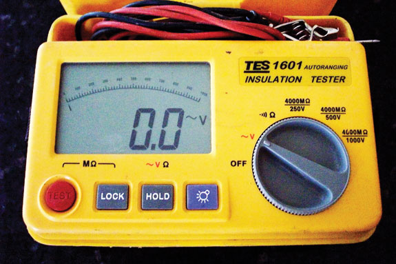
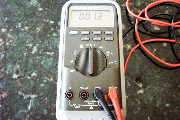
Digital multimeter and megger
The digital multimeter is one of the most common tools we use; linked again to a clamp-on ammeter, we can make various amperage measurements.
The megger is a useful tool used to test the insulation of electrical components for defects (bad wiring, bad motors, etc.). Both these devices have digital displays to show the levels read.
• What problem does the digital multimeter and megger identify? The digital multimeter and megger can be used to determine if a ground fault is present on a circuit.
Any circuit with a leak above 100mA or insulation (L-G or N-G) less than 25Kohms should be verified by a certified electrician for an insulation failure.
• How is the digital multimeter and megger installed? The digital multimeter and megger can be used from the breaker panel and are installed on one circuit at a time to validate if a problem is present.
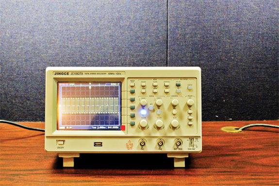
Oscilloscope
An oscilloscope is a tool that allows us to visualize an electric signal. It has a high sampling rate; however, the oscilloscope cannot record over long periods of time.
The operator does have the ability to print the important information.
• What problem does the oscilloscope identify? An oscilloscope, used again with a clamp-on ammeter, can help determine if equipment like variable- speed drives, fencers or electronic lighting generate medium frequency leakage current.
• How is the oscilloscope installed? The ammeter is installed at the breaker panel on the wires feeding the equipment under test. Any readings above 200mA is to be controlled.
As the measurement and analysis of the electrical network is taking place, the measurement figures are constantly being fed via computer back to a team of electrical technicians in the engineering department. These technicians review the data and input the measurements into a software program that confirms that the measurements are “in sync” with known electrical laws.
At the end of the analysis, the data is reviewed in total and a written report is submitted to the producer and his electrician.
This report reviews the electrical network circuit by circuit and points out electrical issues that need to be resolved by the electrician as well as the total sources of stray voltage.
All data is backed up in the report by the actual measurements and charts, thus supporting the analysis and the recommendations. All recommendations made must comply with the National Electrical Code.
Electricity has become an important parameter in our livestock facilities that can greatly affect the profitability of a dairy operation. For that reason, management of the electrical network is a must. PD
Bill Thompson
Agrivolt Inc
bill.thompson@agrivolt.com


